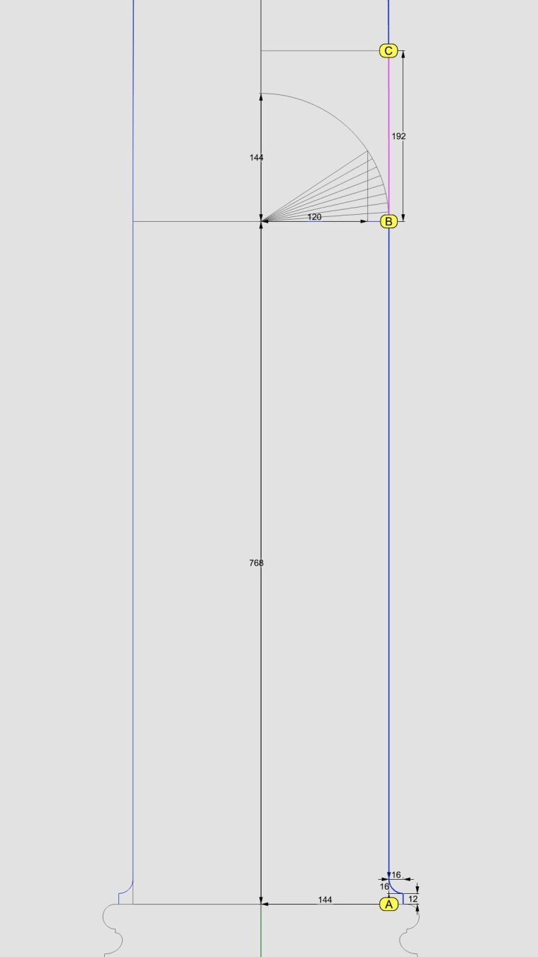


The bottom 1/3 of the #columnShaft for an #IonicColumn is a perfect cylinder. So the line below point B is a straight line.
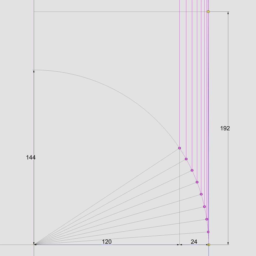
In https://pixelfed.social/p/Splines/791723063470910081, we blended the bottom end of the 60° arc and the top end of the long interpolated curve between points J and K. Now blend the bottom end of the interpolated curve and the top end of the straight line between points B and C to obtain the 3rd and final #NURBS segment for the #primaryProfileCurve of the shaft.
Just like there's a #cavetto and #fillet near the #neck of the shaft, there is a fillet and cavetto near the foot of the shaft. However, there is a subtle difference between the two. The cavetto near the neck is tangential to the blended #NURBS curve that is not a straight line. The profile curve for the cavetto near the foot is tangential to a straight line.
There is a special name for a cavetto that is tangential to a straight line or flat surface, like the two cavetto moldings in the #dado of the #pedestal. It's called a #conge. Another alternate name for the cavetto molding is #cove, which is evocative of "cave" because of its concave profile curve.
Above the neck is a fillet 8 units tall and an #astragal 16 units tall that #Scarlata puts in braces in the column shaft section within his tables of #VignolaProportions, with a note saying they are not counted as part of the shaft but are accounted for as part of the #capital.
I decided to include the top fillet as part of the shaft and keep the astragal with the capital. It does not change the design or alter the proportions in any way, but the inclusion of the fillet makes it more practical for #3DPrinting and #CNCMilling of the neck. This concludes the profile curve for the shaft with a height of 291 parts or 2328 units + 8 for fillet.
The column shaft is tapered in the upper 2/3 due to #entasis whose purpose is to make optical corrections to the shape of the column which, without correction, appeared concave near the top.