

#IonicColumn #Flutes
In https://pixelfed.social/p/Splines/799864068250003272, I mentioned rounding off the radius of the bottom circle, but you don't have to. #CAD tools are perfectly happy working with 15.0728 or even higher precision as they are with 15.
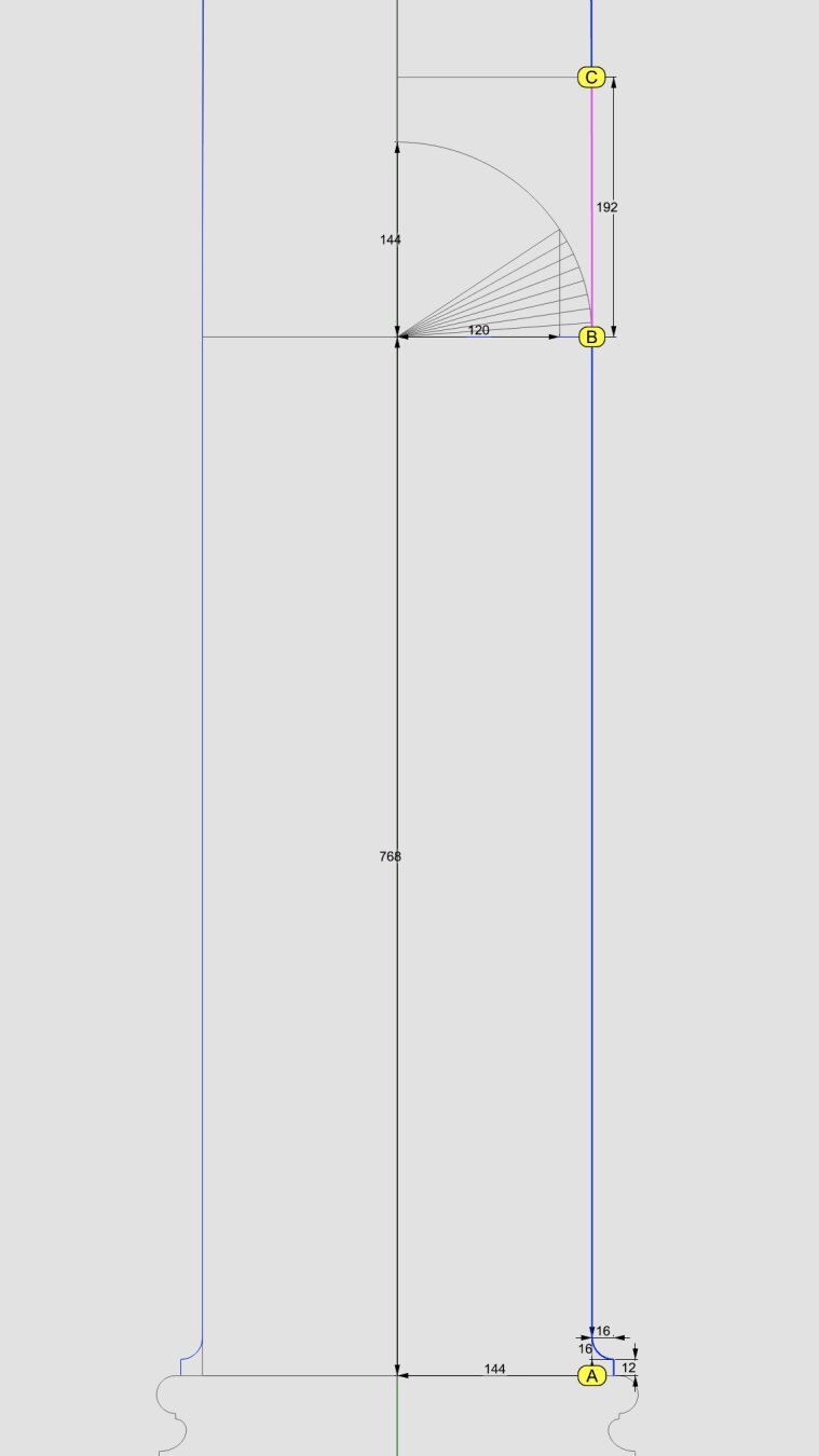
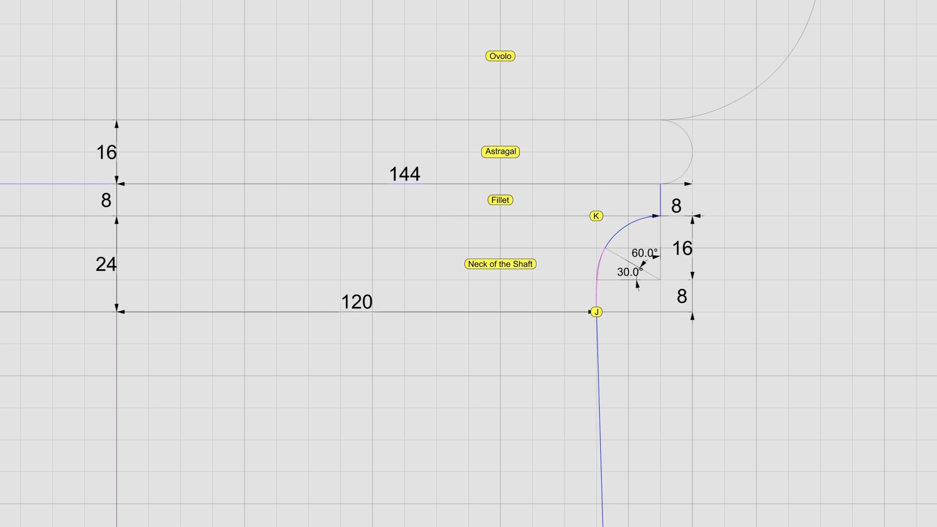
After placing the two circles as described in that post, use the full #primaryProfileCurve of the shaft from https://pixelfed.social/p/Splines/791794072490907090 as a #sweepingRail and the two circles for the flutes as the #sweepingCurves and #sweepOneRail for the body of a single shaft. Close #planarHoles on both ends to get an #airtight solid.
Then draw a sphere at the center of the top circle using the same radius as the circle, and perform a #booleanUnion between the sphere and the flute body.
If you want a round bottom for the flute, repeat the sphere at the center of the larger circle using the same radius (15.0 or 15.0728) and perform another boolean union to get one flute.
Switch to the top view and make 24 copies of the flute (including the original) centered at the column axis and #group the 24 flutes.
Finally, perform a #booleanDifference with the flutes group on a copy of the solid #unadornedShaft to get a fluted variant.
The result is a column shaft with flutes carved out. Save the flutes separately for future reuse.
This concludes the entire #IonicOrder, including all #decorativeElements.
Now we pause and reflect: The whole exercise seemed like one of #art and #sculpture. Where is the #architecture in all of this?
Without a ceiling or a roof, there is no building. Without additional columns or walls, there is no ceiling. So, while we have completed the Ionic Order itself, we only have the first #buildingBlock — a single column.
Next step is to repeat the columns to create a #colonnade, which together with supporting walls or additional colonnades can support a ceiling.
Just like with everything else in design, there are rules of proportion for #intercolumniation, or space between columns.
In https://pixelfed.social/p/Splines/799864068250003272, I mentioned rounding off the radius of the bottom circle, but you don't have to. #CAD tools are perfectly happy working with 15.0728 or even higher precision as they are with 15.
After placing the two circles as described in that post, use the full #primaryProfileCurve of the shaft from https://pixelfed.social/p/Splines/791794072490907090 as a #sweepingRail and the two circles for the flutes as the #sweepingCurves and #sweepOneRail for the body of a single shaft. Close #planarHoles on both ends to get an #airtight solid.
Then draw a sphere at the center of the top circle using the same radius as the circle, and perform a #booleanUnion between the sphere and the flute body.
If you want a round bottom for the flute, repeat the sphere at the center of the larger circle using the same radius (15.0 or 15.0728) and perform another boolean union to get one flute.
Switch to the top view and make 24 copies of the flute (including the original) centered at the column axis and #group the 24 flutes.
Finally, perform a #booleanDifference with the flutes group on a copy of the solid #unadornedShaft to get a fluted variant.
The result is a column shaft with flutes carved out. Save the flutes separately for future reuse.
This concludes the entire #IonicOrder, including all #decorativeElements.
Now we pause and reflect: The whole exercise seemed like one of #art and #sculpture. Where is the #architecture in all of this?
Without a ceiling or a roof, there is no building. Without additional columns or walls, there is no ceiling. So, while we have completed the Ionic Order itself, we only have the first #buildingBlock — a single column.
Next step is to repeat the columns to create a #colonnade, which together with supporting walls or additional colonnades can support a ceiling.
Just like with everything else in design, there are rules of proportion for #intercolumniation, or space between columns.